I. Project introduction and construction
The intelligent control system of coke oven heating is designed for the 5.5m stamp charging coke oven. The system aims to save gas, stabilize coke quality and facilitate manual operation. Through intelligent control of coke oven heating process and coordination of four car interlocking system, the coking production process is comprehensively and intelligently controlled.
The scope of the project includes the production site of the coke oven, from the main body of the coke oven to fixed facilities such as gas pipelines, flues, risers, and smoke separation ducts, as well as four vehicles (coal loading vehicles, coke pushing vehicles, coke quenching vehicles, coke blocking vehicles), Mechanical facilities such as switches. The manageable objects include the main body of the coke oven and various gas pipes, flues, and four-car equipment; the materials include heating gas, air, coke cake, exhaust gas, and waste gas.
uilding progress:
Hunan Qianmeng Industrial Intelligent System Co., Ltd. has signed the contract on May 3, 2018 and completed the acceptance on October 6, 2018.
Second, the implementation plan
The project is divided into various sub-systems for implementation, including the stand-fire flame temperature measurement system, the riser temperature measurement system, the gas single-pipe automatic transformation system, and the four-car interlocking system implementation plan
1.Construction of temperature measurement system for vertical fire tunnel
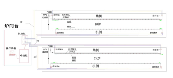
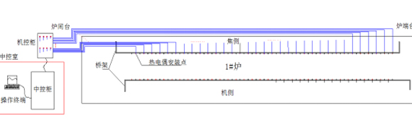
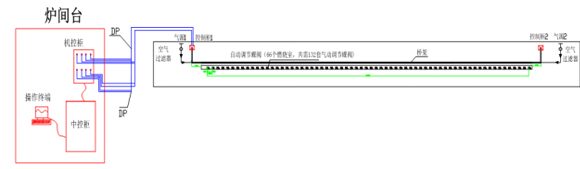
Figure 21 Overall layout of full and semi-installed infrared temperature measurement in vertical fire tunnel
The installation of 1 # furnace infrared thermometer in the figure above is a schematic diagram of the full installation of the thermometer. There are 4 control cabinets on the coke side and the machine side of the furnace end table and the furnace table. There are 102 temperature measurement points in each furnace. (For example, 51 thermometers on the focal side, "machine control cabinet 1" is connected to nearly 26, and "machine control cabinet 3" is close to 25, and the machine side is similar). At the same time, the air source or nitrogen source is connected to the furnace table and the end table. The air source needs to be equipped with 2 sets of air filters on the coke side, a total of 4 sets of air filters. The air source and nitrogen source can be automatically switched. Backside infrared thermometer.
The backflushing gas is mainly nitrogen, and clean and dry instrument wind is used as a backup. Manual remote switching is implemented according to the needs of the site to ensure that the backflushing system has continuous wind.
The DN50 gas pipe interface needs to be connected near the coke oven, with a flanged stop valve, and an air storage tank location (1000mm in diameter and 2500mm in height) is reserved. Air source pressure is not less than 0.8Mpa. The air volume is about 40m³ / h.
(1) Partial installation drawing
Figure 22 Installation layout of the infrared thermometer in the fire tunnel
(2) Site construction drawing
Host computer interface
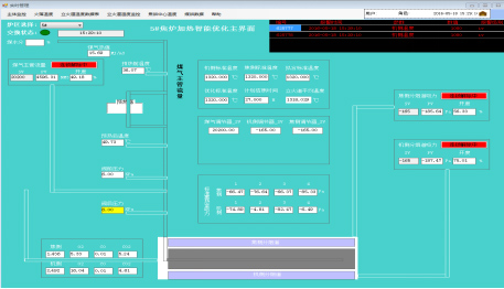
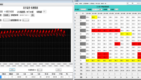
Figure 23 Average temperature, change trend, and statistical table
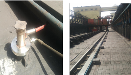
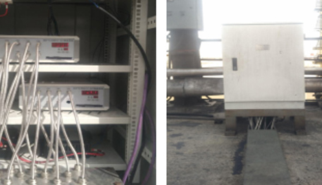
Hardware physical map
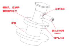
Figure 24 Demonstration diagram of temperature measurement point installation
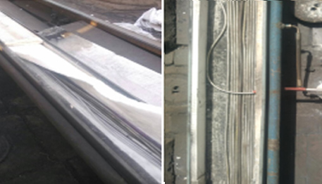
Figure 25 Demonstration diagram of infrared thermometer fiber
Figure 26 Infrared thermometer control cabinet
2. Construction of temperature measurement system for riser
1) Overall installation layout
Figure 27 Overall layout of riser thermocouple installation
The machine control cabinet is arranged in the furnace room to connect all thermocouples; the machine control cabinet is connected to the central control cabinet of the central control room through the DP bus.
2) Partial installation drawing
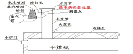
Installed near the bridge pipe connection, the temperature of the waste gas is lower than that of the riser pipe, which can prolong the life of the thermocouple, save materials and facilitate installation.
Figure 28 Schematic diagram of the thermocouple component mounting part (near the bridge tube connection)
3) Site construction drawing
Host computer interface
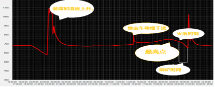
Figure 29 Trend of crude gas temperature with coking time
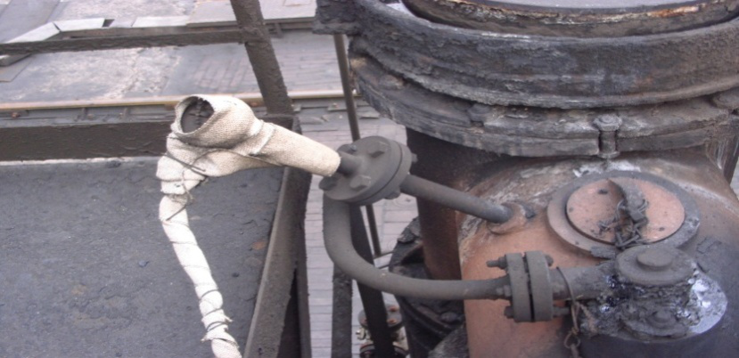
Site physical map
Figure 30 Demonstration point 2—Bridge tube
3.Automated reconstruction of single gas pipe
1) Overall installation layout
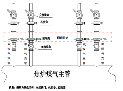
Figure 33 Overall installation layout of coke oven gas single tube reconstruction
2) Reconstruction diagram
There is a short joint between the single tube orifice plate box and the addition and subtraction of the Cork for transformation. The workload is small, and the existing single tube structure will not be changed.
The control center sends a signal to the positioner, the positioner works to connect the air source, and the opening degree of the butterfly valve is adjusted to a suitable position by a pneumatic actuator (if there is no air source and no electricity, the manual mechanism can be adjusted manually To adjust the butterfly valve opening). When the opening degree of the butterfly valve is adjusted to the specified position, the positioner cuts off the power and keeps the butterfly valve in this position. Then the signal is transmitted to the control center, so as to realize the automatic adjustment of the single tube.
The modified sealing device is also a sealing device using the existing pipeline.
Fig. 32 Schematic diagram of coke oven gas single tube transformation-(short section modification)
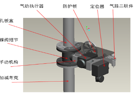
Figure 33 Structure of the regulating valve
Figure 34 Overall bird's eye view
The position of the bridge can be in the upper or lower part, the specific position is subject to the scene.
Figure 34 Pneumatic actuator pneumatic circuit diagram
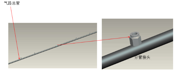
The gas path is arranged such that the center of the furnace body is divided into two gas path headers, and then a pneumatic regulating butterfly valve connected to each single tube through a pipe joint and a gas tube.
2) Site construction drawings
Host computer interface
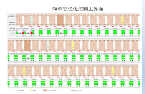
Figure 34 single tube optimization control interface
The interface includes a single hole fire fall time abnormal prompt, an oven time reminder, a vertical fire tunnel temperature abnormal prompt, a single tube adjustment automatic means switch, and exchange signal display.
Hardware physical map
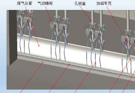
Figure a before transformation Figure b after transformation
Figure 35 Site effect diagram of single tube reconstruction-(short section reconstruction)
4.Four-car interlocking system
Host computer interface
Figure 31 Real-time monitoring diagram of four-vehicle interlocking system
Figure 32 Focusing plan
The four-car interlocking system can provide coke oven coke push and coal loading data for coke oven heating. The coke oven heating system analyzes coke oven time and adjusts the demand for coke oven gas. The stroke of the coke rod is conducive to the temperature measurement of the coke cake to determine the temperature of each position of the coke cake. The temperature of the coke cake is helpful to deduce the corresponding heating situation of the vertical fire tunnel. The system can be upgraded to increase the unit of coke pusher and coke quencher, which is convenient for the management of coke oven production.
Third, the technical route
The system includes a data acquisition subsystem, a gas supervisor automatic adjustment subsystem, a flue gas suction automatic adjustment subsystem, a gas collection process intelligent control subsystem, and a four-car interlocking subsystem. The system framework is shown in the figure:
Figure 1 system structure diagram
The system uses industrial network environmental protection detection system, laboratory system, dcs system and other third-party systems in the factory for data exchange; and installs online collection equipment data, mainly including straight-line temperature, flue gas exhaust gas oxygen content zirconia, rising tube Gas temperature, opening degree of single pipe control valve, etc.
After the intelligent calculation center comprehensively analyzes the data, it intelligently adjusts the set value of the gas main, the set value of the suction of the flue gas, the opening degree of the single-pipe regulating valve, and optimizes the standard temperature to ensure stable and uniform temperature in the coking process. The intelligent computing center communicates with the DCS system to achieve data sharing and bumpless switching.
4. Project achievements, implementation results and experience summary
Project achievements and implementation results
After the project is put into use, it meets environmental protection production, and the workload of temperature regulation and temperature measurement is significantly reduced, and the gas saving effect is obvious. The specific effects are as follows:
1. Under the condition of the same gas calorific value, standard temperature and coal blending level, the gas can be saved by about 5% through the main pipe control.
2. Under normal production conditions such as no clogging of the coke oven gas pipeline, stable gas flow meter, normal regulating valve, and sufficient gas pressure, the average temperature of the whole furnace is ± 7 ° C.
3. Reduce nitrogen oxides by about 30% under normal operating conditions.
Lessons learned:
Coking intelligent manufacturing projects, based on automated equipment, add the necessary online sensing, and through working condition analysis and pre-judgment, the focus is on adaptive control to meet on-site working condition changes, and automatic accumulation of knowledge base to achieve coking production. Intelligence and management intelligence.